The open-circuit voltage is the voltage in the current–voltage characteristics of a solar cell that is defined where the current is zero. That means that the (internal) charge carrier generation and recombination rates are equal, so that no net current can flow out of the device.
We can simply rearrange the ideal diode equation and solve for the open-circuit voltage.  The ideal diode equation was discussed with respect to the ideality factor in this post. The current density is given as
 ,
,
with  the voltage,
  elementary charge,
  thermal voltage,
  the recombination ideality factor,
  the dark saturation current, and
  the photogenerated current. For simplicity, the latter is chosen to be voltage independent, and therefore is equal to the short-circuit current
  .
.
As the open-circuit voltage is determined at zero net current,  , we get
 ,
,
which we can rearrange to yield the open-circuit voltage
 .
.
Here,  is the photocurrent due to solar illumination, and the dark saturation current density is due to excitation of thermal “black body” photons from the ambient at, say, room temperature. In the simplest case – in the dark where
  – we see that
  , too. Generally, the thermal generation leading to is much weaker than the solar generation , therefore
 .
.
is usually a very good approximation.
This simple equation to describe the open-circuit voltage is very general and can describe (outside of the shunt region, which is not considered here) very different solar cell technologies correctly. The reason is that many parameters that differ for different semiconductors are accounted for. So what determines the open-circuit voltage?
At a given temperature, the open circuit voltage is determined by
– ,
– , and
–  (which was discussed previously)..
The generation current density

which means it is given by how much of the solar photon flux of the sun,  , is converted into electrons – which is described by the external quantum efficiency
  . The
. The  includes reflection losses, the absorptance (in the simplest case 0 below the bandgap and 1 for energies at or higher than the band gap
  ), and charge collection losses (for instance due to the transport resistance). Essentially, the higher the bandgap , the higher – which leads to a higher open-circuit voltage.
The dark saturation current density in an ideal solar cell without non-radiative losses is essentially given by

The only difference to the equation for is that the photons do not come from the sun anymore, but from the ambient (note the subscript a;). This  is just Planck’s law to describe thermal radiation from black bodies, so everything “earthly” around the solar cell that emits at the current temperature
  (or
(or  , the temperature of the ambient). While the sun that generates can also be well approximated by a block body and Planck’s law – assuming a black body temperature of the sun of
  , usually the temperature of the ambient that leads to corresponds to the solar cell temperature… for instance,
  .
.
With this in mind, we can maybe see already what determines the temperature dependence of the open-circuit voltage! In
 ,
,
there is an explicit temperature dependence in the prefactor, , which “promises” increasing open-circuit voltages at higher temperatures, but from measurements we know that the opposite happens: the open-circuit voltage increases towards lower temperatures!
Except for temperature-dependent changes in the charge collection (or bandgap), is (solar cell) temperature independent. The ideality factor can depend on temperature (and, in organic solar cells, even light intensity dependence [Saladina 2023]), but does not dominate the temperature dependence of  . The real “culprit” is indeed the very important dark saturation current density , which describes charge carrier generation (and recombination!) across the bandgap by thermal photons (plus, in real systems, non-radiative processes)!
When we approximate the equation for the ideal dark saturation current density (ideal, because we again neglect non-radiative losses) from above – using the Boltzmann approximation instead of the Bose-Einstein statistics that are featured in Planck’s law – we can describe the temperature dependence of :
 .
.
The temperature here is, again, the solar cell’s and the ambient temperature is equal to it. We assume for simplicity (again a pretty good approximation) that the bandgap is not (or only very weakly) temperature dependent. The prefactor  is essentially the dark saturation current density at infinite temperature, when the effective density of states is (hypothetically) completely filled, which is reduced by lower temperatures: the thermal photons from the ambient generate electron–hole pairs across the bandgap, increasing and – as it is in the denominator of the equation for – decreasing the open-circuit voltage at higher temperatures. We can make this result more transparent when entering the temperature dependent dark saturation current density into the equation for the open-circuit voltage: (For simplicitly, I left the explicit temperature dependence of the ideality factor out, writing
  instead of
  .)
.)


We see now that the maximum open circuit voltage at zero temperature (in a system described by classical Boltzmann approximation,  for a-Si H solar cell.jpg") i.e. without the energetic disorder that is an important topic in organic solar cells) is given by the (effective) bandgap of the device – usually the bandgap of the active layer material. The open-circuit voltage is reduced at higher temperatures(!) despite the plus sign after the term
i.e. without the energetic disorder that is an important topic in organic solar cells) is given by the (effective) bandgap of the device – usually the bandgap of the active layer material. The open-circuit voltage is reduced at higher temperatures(!) despite the plus sign after the term  : the dark saturation current density at infinite temperature is larger than , and the argument of a natural logarithm with argument smaller than one is negative. This means that the second term on the right-hand side is negative, and decreases at higher temperatures.
I’ll leave it here for now, with two comments: first, there is more to be said about why one always should use the ideality factor in the equation  that gives the temperature dependence of the dark saturation current density! And second, the impact of energetic disorder on is very important and leads to changes – the devil in the details;)


 is changing with time during the measurement – no matter if the method is a large signal (OCVD) or small signal method (TPC, IMVS):
 – and the second term a contribution coming from the response of charge due to the measured signal of the experimental technique: the time variation of the voltage as response to a time dependent light signal (pulsed or modulated). If the latter capacitive term becomes dominant, the recombination lifetime cannot be determined anymore, as is hidden behind the RC time.
 vs
vs  are different and, in this case, a measure of the recombination order.
 is the
  is the voltage dependent capacitance, which can be estimated (as lower bound) by the geometric capacitance of the active layer,
  , with the dielectric constants (relative and vacuum) and
  the active layer thickness (you could also include organic transport layers, but probably not PEDOT:PSS as it has a relative dielectric constant
  3). The generation current density can be approximated, in most cases, by the short circuit current density
  (unless the
  and
and  and
and 
 after Kiermasch 2018, compared to the measured time constants by IMVS,
  . Except for, maybe, low temperatures, the RC times dominate the measured signal at high open circuit voltages, whereas the shunt limits the lifetime determination at lower open
 and holes
  are photogenerated pair wise, the respective excess charge carrier concentrations are symmetric,
  . Then a recombination rate
  ,
, could be a Langevin prefactor – more on that later. In a transient experiment with a photogenerating, short laser pulse at
  , the continuity equation for charge carriers (here, e.g. electrons) under open circuti conditions (no external current flow, for instance if the experiment is done on a thin film without electrodes)

 (as the generation was only at

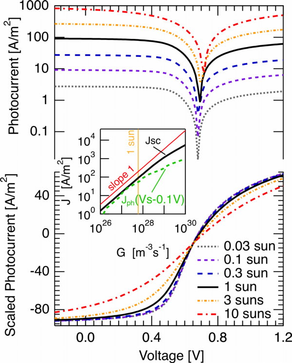


 it is pretty low in state-of-the-art bulk heterojunction solar cells, and has therefore been neglected. For now, lets concentrate on the contribution from polaron pair dissociation. For the sample shown in the figure, the separation yield approaches 60% at short circuit current (at about 0.6V on the rescaled voltage axis, 0V corresponding to the flatband case). The question is, why is it so high in polymer-fullerene solar cells, considering that a charge pair has a binding energy og almost half an electron Volt at 1 nm distance, and that recombination is on the order of nanoseconds [