
In at least two previous posts (Picture Story and How do organic solar cells function – Part 1), I highlighted the field dependence of the photocurrent in organic solar cells, and its connection to the polaron pair dissociation. Actually, there is more to it.
The field dependence of the photocurrent is due to different contributions:
- polaron pair dissociation (bulk heterojunctions and bilayers)
- polaron recombination (mostly bulk heterojunctions)
- charge extraction (bulk heterojunctions and bilayers)
An experimental curve of the photocurrent of a P3HT:PCBM solar cell is shown in the figure (relative to the point of optimum symmetry, as described by [Ooi 2008]. The symbols show our experimental data, the green curve a fit with two of the contributions mentioned above: polaron pair dissociation (after [Braun 1984]) and charge extraction (after [Sokel 1982]). Both models are simplified, but more on that later. Polaron recombination has been covered before (here and here); 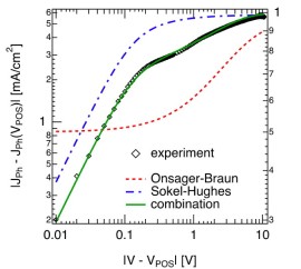 it is pretty low in state-of-the-art bulk heterojunction solar cells, and has therefore been neglected. For now, lets concentrate on the contribution from polaron pair dissociation. For the sample shown in the figure, the separation yield approaches 60% at short circuit current (at about 0.6V on the rescaled voltage axis, 0V corresponding to the flatband case). The question is, why is it so high in polymer-fullerene solar cells, considering that a charge pair has a binding energy og almost half an electron Volt at 1 nm distance, and that recombination is on the order of nanoseconds [Veldman 2008].
A powerful way to gain new insight into the mechanisms governing polaron pair dissociation is by using Monte Carlo simulations. We recently applied this technique to explain the origin of the high polaron pair dissociation yield found experimentally in polymer-fullerene solar cells [Deibel 2009a]. We will give an introduction to Monte Carlo simulations another time – for now only stating that some information can be found in our paper, and more details on the principle in [Houili 2006] – and focus on the physics for now.
In the figure below, the simple cubic lattice representing the donor-acceptor blend is shown on the left hand side. Polaron pairs are generated by setting a positive charge on the polymer (the donor), and a certain distance away (e.g., the nearest neighbour distance of 1nm) a negative charge on the fullerene (the acceptor). Every site has a certain energy chosen from a Gaussian distribution of states, and charges are subject to the external electric field and the Couloumbic attraction (or repulsion). The charges move by a hopping process as described by the Miller-Abrahams hopping rate [Miller 1960]. On the right hand side, the polaron pair dissociation yield is shown in dependence on the electric field (log-log Plot). The simulated curves (dotted) are shown for two different effective polaron pair lifetimes, the solid red line corresponds to the polaron pair contribution as extracted from the photocurrent in the topmost figure. The yellow rectangle denotes the internal field under solar cell short circuit conditions, i.e., the highest field usually found in a working organic solar cell. Clearly, the simulations underestimate the polaron pair separation yield by more than one order of magnitude.

Why is the discrepancy between simulation and experiment so large? What is the origin of the high experimental polaron pair dissociation yield?
Several possible explanations come to mind,
- a high local mobility could have a stronger impact, either due to fullerene nanocrystals [Veldman 2008] on which charges are delocalised, or – as the evidence for fullerene nanocrystals is somewhat debated [Deibel 2009a] – polymer chains [Hoofman 1998 (exp)]
- excess energy from hot polaron pairs [Ohkita 2008 (exp)]
- local dielectric constant [Szmytkowski 2009 (analytic)]
One group has performed a Monte Carlo simulation to check the influence of nanocrystals on polaron pair dissociation,
- high local mobility of charges in nanocrystals [Groves 2008 (sim)],
considering ordered domains in the otherwise disordered, low-mobility donor-acceptor blends. However, while the high experimental yield could almost be reached, the donor and acceptor “grains” were very large, and the polaron-pair lifetimes orders of magnitude higher than determined experimentally.
In order to contribute to this issue, we considered
- delocalisation of charges along the effective conjugation length polymer chains [Deibel 2009a (sim)],
following the experiments of Hoofman et al. We modified our Monte Carlo simulation accordingly, as shown in the figure below:
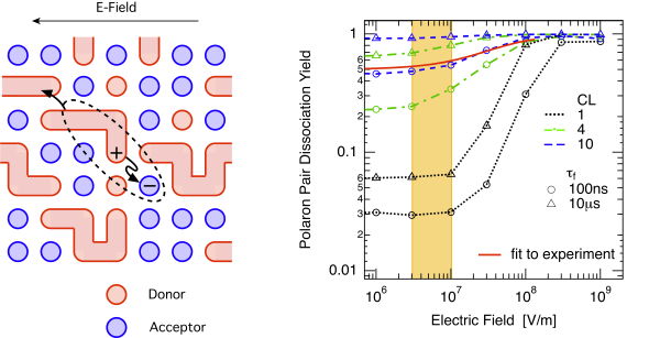
The long polymer chains are shown schematically on the left hand side, the resulting field-dependent polaron-pair dissociation yield (log-log) is shown on the right hand side. An effective conjugation length (CL) of 4 or 10 monomer units, which is easily reached in the current synthesis of conjugated polymers, yields a strong increase of the separation yield up to 60% to 90% dissociation yield at moderate fields of below 107 V/m, as found in working organic solar cells.
Thus, the highly efficient polaron-pair dissociation can be explained by delocalised charge carriers within conjugated segments of the polymer chain. The resulting local charge carrier mobility is much larger than the macroscopic one. Together with the reduced Coulomb attraction due to the accordingly increased initial polaron-pair radius, the high on-chain mobility is essential to explain the high polaron- pair separation yield. These values correspond to recent experimental findings, as also indicated by the solid red line, the polaron pair contribution as extracted from the photocurrent in the topmost figure. Thus, we believe the delocalisation along the conjugated polymer chains to be a dominant contribution to polaron pair separation, although other contributions listed above can certainly also play a role.
More on photocurrent, polaron pair dissociation and Monte Carlo simulations later;-)

Yeah absolutely, I agree with what you say above. I haven’t published the data yet but some of my experiments suggest the delocalisation area of the polaron cation in P3HT is around 30 nm in diameter (assuming a sphere shape to the polaron). This is pretty big and like you say could explain the weak coulombic interaction between hole and electron. I think local dielectric constant may play a role as well but not sure. From my point of view an electric field is not necessary to get near unity free electrical charge carrier generation in P3HT:PCBM.
That sounds like very interesting work, looking forward to see it! A colleague told me that the current P3HTs from BASF can have conjugation lengths of 20 or more. What also might influence your large delocalisation range is the interchain delocalisation in the P3HT lamellae reported by Sirringhaus et al, Nature 401, 685 (1999). We did not consider interchain delocalisation in our simulation, it would further improve the polaron pair dissociation yield, also resulting in an even weaker field dependence. However, maybe not quite — but almost — unity.