Return of the transport resistance: what Jphoto vs. Veff really tells you

The last two times I wrote about transport resistance as a voltage-loss (or, depending on how you like to look at it, current-loss) mechanism in organic solar cells – in 2022 and 2025 – I mostly talked about fill factor: how a low active-layer conductivity bends the illuminated j(V) curve around V_\mathrm{oc}, and how the resulting gap between FF and pseudo-FF is often larger than the recombination loss itself, even in record-efficiency devices. Moon over Hoher Ifen from Hirschegg.This time I want to show you that a plot that is very common in today’s literature does not make much sense for today’s high-efficiency organic solar cells. I am talking about the plot of photocurrent – the difference between illuminated and dark current of a solar cell – vs what is called “effective voltage”, i.e., J_\mathrm{ph} vs. V_\mathrm{eff}. I mentioned this in a talk on transport resistance that I gave at the SAMSEC in Berlin in July 2025. I want to write this post to address potential misconceptions concerning this plot.

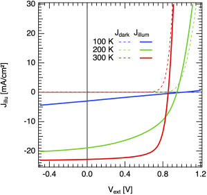
If you look at the current–voltage characteristics of state-of-the-art organic solar cells, as shown in the plot below, you can observe that dark and illuminated j(V) curves cross. The voltage at which they cross is often called V_0: it is the compensation voltage, and by definition, the photocurrent there is zero, J_\mathrm{ph}=0. It is important to point out that in the ideal diode equation (briefly mentioned in this earlier post, equation “(*)”), this case never occurs: there, due to the superposition principle, the illuminated curve is just a shifted-down version of the dark current, by the generation current density J_\mathrm{gen}. Thus, in the ideal case, dark and illuminated curve never meet! Fig0 JVT dark+illum pm6y6.

So, the question I hear you asking: why do the experimental dark and illuminated current densities cross?

For the field of organic photovoltaics, this question was first addressed by the Blom group, in Mihailetchi 2004. At this time, organic solar cells reached power conversion efficiencies of only 2 or 3%. So, Valentin Mihailetchi plotted the photocurrent density of a PPV:PCBM organic solar cell, J_\mathrm{ph} = J_\mathrm{illum} - J_\mathrm{dark}, against the effective voltage V_\mathrm{eff} = V_0 - V, where V is the applied voltage. As result, one gets a photocurrent curve that rises steeply and then flattens into a plateau which corresponds to the solar cells’ maximum photocurrent. The authors interpreted this result as follows:

“The photocurrent in conjugated polymer-fullerene blends is dominated by the dissociation efficiency of bound electron-hole pairs at the donor–acceptor interface. A model based on Onsager’s theory of geminate charge recombination explains the observed field and temperature dependence of the photocurrent in PPV:PCBM blends. At room temperature only 60% of the generated bound electron-hole pairs are dissociated and contribute to the short-circuit current.”

Continue reading “Return of the transport resistance: what Jphoto vs. Veff really tells you”

How to see the temperature dependence of the open-circuit voltage from the ideal diode equation?

The open-circuit voltage is the voltage in the current–voltage characteristics of a solar cell that is defined where the current is zero. That means that the (internal) charge carrier generation and recombination rates are equal, so that no net current can flow out of the device.

We can simply rearrange the ideal diode equation and solve for the open-circuit voltage. The ideal diode equation was discussed with respect to the ideality factor in this post. The current density is given as

j(V)=j_0 \left(\exp\left(\frac{eV}{n_{id}kT}\right)-1\right) - j_\text{gen},

with V the voltage, e elementary charge, kT thermal voltage, n_\mathrm{id} the recombination ideality factor, j_0 the dark saturation current, and j_\mathrm{gen} the photogenerated current. For simplicity, the latter is chosen to be voltage independent, and therefore is equal to the short-circuit current j_\mathrm{sc}.

As the open-circuit voltage is determined at zero net current, j(V_\mathrm{oc}) = 0, we get

j(V_\mathrm{oc}) = 0 = j_0 \left(\exp\left(\frac{eV_\mathrm{oc}}{n_{id}kT}\right)-1\right) - j_\text{gen},

which we can rearrange to yield the open-circuit voltage

V_\mathrm{oc} = \frac{n_{id}kT}{e} \ln \left( \frac{j_\text{gen} + j_0}{j_0} \right).

Here, j_\text{gen} is the photocurrent due to solar illumination, and the dark saturation current density j_0 is due to excitation of thermal “black body” photons from the ambient at, say, room temperature. In the simplest case – in the dark where j_\text{gen} = 0 – we see that V_\mathrm{oc} = 0, too. Generally, the thermal generation leading to j_0 is much weaker than the solar generation j_\text{gen}, therefore

V_\mathrm{oc} \approx \frac{n_{id}kT}{e} \ln \left( \frac{j_\text{gen}}{j_0} \right).

is usually a very good approximation.

This simple equation to describe the open-circuit voltage is very general and can describe (outside of the shunt region, which is not considered here) very different solar cell technologies correctly. The reason is that many parameters that differ for different semiconductors are accounted for. So what determines the open-circuit voltage?

Continue reading “How to see the temperature dependence of the open-circuit voltage from the ideal diode equation?”

Links

Some links collected over the last months.

I will be at the ISCPAC 2016 meeting next week. In case you are also there, meet up:-)

[2016-06-07 Some Updates in the afternoon;-)]

US American Energy Frontier Reseach Centers announced

The US Department of Energy is to fund 46 so called Energy Frontier Research Centers (EFRCs) with 777 million dollars over the course of the next five years (see news here). OffspringQuite a commitment to basic research in times of a global economic crisis &ndash although the decision has been taken years before, with thematic workshops starting in 2003.

Some of the centers will focus on photovoltaic energy conversion, partly with a strong focus on organics!

  • Center for Interface Science: Hybrid Solar-Electric Materials, University of Arizona (Director: Neil R. Armstrong)
  • Center for Inverse Design, National Renewable Energy Laboratory in Colorada (Director: Alex Zunger)
  • Center for Excitonics, Massachusetts Institute of Technology (Director: Marc Baldo)
  • Polymer-Based Materials for Harvesting Solar Energy, University of Massachusetts (Director: Thomas Russell)
  • Solar Energy Conversion in Complex Materials, University of Michigan (Director: Peter Green)
  • Solar Fuels and Next Generation Photovoltaics, University of North Carolina (Director: Thomas Meyer)
  • The Center for Advanced Solar Photophysics, Los Alamos National Laboratory (Director: Victor Klimov)
  • Re-Defining Photovoltaic Efficiency Through Molecule-Scale Control, Columbia University (Director: James Yardley)
  • Understanding Charge Separation and Transfer at Interfaces in Energy Materials and Devices, University of Texas (Director: Paul Barbara)

The list can be found here, and there are also details available.

Well, strong competition coming up for us European researchers… but what could be better for driving a field forward? ;-)

Add to Connotea

Mobility and Efficiency of Polymer Solar Cells

Joshua TreeDisordered organic materials inhibit charge carrier mobilities which are orders of magnitude lower than for inorganic crystals. First thing missing in disordered matter is the regularly ordered lattice of atoms, where the charge carriers can delocalise, leading to band transport. Second thing is the generally lower interaction between adjacent molecules, which is due to weaker bonding and larger distances. The transfer integral, the value of which goes exponentially down with distance, to get from one to the other molecule is too low for delocalisation. Thus, in terms of charge carrier mobility, think 10-2cm2/Vs for disordered organics (if you are lucky) vs. at least 102cm2/Vs for ordered inorganics.

How much does a weak charge transport limit the performance of organic solar cells? How bad is it?

Continue reading “Mobility and Efficiency of Polymer Solar Cells”

Inkjet Printing of Inorganic Solar Cells

Last week, the german company Roth and Rau – supplier of plasma process systems for the photovoltaics industry – had Newbury Street, Bostona press release: they just finished the installation of a new production line for inkjet printing of silicon solar panels, together with Innovalight. See here (or in german here). Innovalight has developed the silicon ink technology in recent year, in collaboration with NREL and others. Low level of details, as typical for press realeases, but certainly interesting. And a competitor for printed organic solar cells even before they are in the production stage, even if on track.

Add to Connotea

To be improved: Lifetime of Organic Solar Cells

I just came across this press release from the before-mentioned organic solar cell company Konarka. Boston Evening OneI mention it particularly, as our research group participates in this BMBF project to improve the stability of organic solar cells.

A somewhat older press release (see here and here) by the belgian research institute IMEC shows how they managed to improve the stability of the donor material, a conjugated polymer. The improvement is apparent from electrical characteristics and TEM images.

Not being quite as fancy as efficiency improvements, the lifespan of organic solar cells is probably more important for a ssuccessful commercialisation. As you know now that we are “officially” involved, stay tuned: this topics interests me from a fundamental research perspective.

Add to Connotea

Mass Production of Plastic Solar Cells

LookTechnology Review has a piece on the first commercial fab for organic solar cells.

In a significant milestone in the deployment of flexible, printed photovoltaics, Konarka, a solar-cell startup based in Lowell, MA, has opened a commercial-scale factory, with the capacity to produce enough organic solar cells every year to generate one gigawatt of electricity, the equivalent of a large nuclear reactor.

Read it here, or the corresponding Konarka press release.

Thanks to Henning for the link.

Add to Connotea

Trimolecular Recombination … really?

As you might already have guessed, I am interested in loss mechanisms in organic photovoltaics. Despite considering the impact of recombination on the solar cell performance, also the physical origins are challenging… and many open questions remain.

Just a view days ago, there was another publication about recombination of free polarons (free carriers) – also called nongeminate recombination *1 – more specifically, trimolecular recombination. Abendstimmung im Vogelschutzgebiet GarstadtYou might remember that, a while ago, I already mentioned third order recombination, including a reference to private communications with Prof. Juska and another recent paper by the Durrant group [Shuttle 2008]) as well as a potential candidate for its origin. The new paper [Juska 2008] uses three different experimental methods, including photo-CELIV, to measure the temperature dependence of the trimolecular recombination rate in polymer:fullerene solar cell. The authors mention very briefly a possible mechanism responsible for the third order recombination, Auger processes. Shuttle et al. argue in their paper that a bimolecular recombination with a carrier concentration dependent prefactor could be the origin, in particular as they observe a decay law proportional to n2.5-n3.5, depending on the sample. We are also in the game, an accepted APL awaiting its publication (preprint here) Update 20.10.2008: now published online [Deibel 2008b]. We rather tend to believe the explanation by Shuttle, but that’s just an assumption at the present stage: the generally low recombination rate could also be due to a rather improbable process.

Continue reading “Trimolecular Recombination … really?”