Return of the transport resistance: what Jphoto vs. Veff really tells you

The last two times I wrote about transport resistance as a voltage-loss (or, depending on how you like to look at it, current-loss) mechanism in organic solar cells – in 2022 and 2025 – I mostly talked about fill factor: how a low active-layer conductivity bends the illuminated j(V) curve around V_\mathrm{oc}, and how the resulting gap between FF and pseudo-FF is often larger than the recombination loss itself, even in record-efficiency devices. Moon over Hoher Ifen from Hirschegg.This time I want to show you that a plot that is very common in today’s literature does not make much sense for today’s high-efficiency organic solar cells. I am talking about the plot of photocurrent – the difference between illuminated and dark current of a solar cell – vs what is called “effective voltage”, i.e., J_\mathrm{ph} vs. V_\mathrm{eff}. I mentioned this in a talk on transport resistance that I gave at the SAMSEC in Berlin in July 2025. I want to write this post to address potential misconceptions concerning this plot.

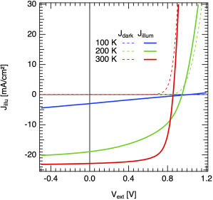
If you look at the current–voltage characteristics of state-of-the-art organic solar cells, as shown in the plot below, you can observe that dark and illuminated j(V) curves cross. The voltage at which they cross is often called V_0: it is the compensation voltage, and by definition, the photocurrent there is zero, J_\mathrm{ph}=0. It is important to point out that in the ideal diode equation (briefly mentioned in this earlier post, equation “(*)”), this case never occurs: there, due to the superposition principle, the illuminated curve is just a shifted-down version of the dark current, by the generation current density J_\mathrm{gen}. Thus, in the ideal case, dark and illuminated curve never meet! Fig0 JVT dark+illum pm6y6.

So, the question I hear you asking: why do the experimental dark and illuminated current densities cross?

For the field of organic photovoltaics, this question was first addressed by the Blom group, in Mihailetchi 2004. At this time, organic solar cells reached power conversion efficiencies of only 2 or 3%. So, Valentin Mihailetchi plotted the photocurrent density of a PPV:PCBM organic solar cell, J_\mathrm{ph} = J_\mathrm{illum} - J_\mathrm{dark}, against the effective voltage V_\mathrm{eff} = V_0 - V, where V is the applied voltage. As result, one gets a photocurrent curve that rises steeply and then flattens into a plateau which corresponds to the solar cells’ maximum photocurrent. The authors interpreted this result as follows:

“The photocurrent in conjugated polymer-fullerene blends is dominated by the dissociation efficiency of bound electron-hole pairs at the donor–acceptor interface. A model based on Onsager’s theory of geminate charge recombination explains the observed field and temperature dependence of the photocurrent in PPV:PCBM blends. At room temperature only 60% of the generated bound electron-hole pairs are dissociated and contribute to the short-circuit current.”

Continue reading “Return of the transport resistance: what Jphoto vs. Veff really tells you”

How to see the temperature dependence of the open-circuit voltage from the ideal diode equation?

The open-circuit voltage is the voltage in the current–voltage characteristics of a solar cell that is defined where the current is zero. That means that the (internal) charge carrier generation and recombination rates are equal, so that no net current can flow out of the device.

We can simply rearrange the ideal diode equation and solve for the open-circuit voltage. The ideal diode equation was discussed with respect to the ideality factor in this post. The current density is given as

j(V)=j_0 \left(\exp\left(\frac{eV}{n_{id}kT}\right)-1\right) - j_\text{gen},

with V the voltage, e elementary charge, kT thermal voltage, n_\mathrm{id} the recombination ideality factor, j_0 the dark saturation current, and j_\mathrm{gen} the photogenerated current. For simplicity, the latter is chosen to be voltage independent, and therefore is equal to the short-circuit current j_\mathrm{sc}.

As the open-circuit voltage is determined at zero net current, j(V_\mathrm{oc}) = 0, we get

j(V_\mathrm{oc}) = 0 = j_0 \left(\exp\left(\frac{eV_\mathrm{oc}}{n_{id}kT}\right)-1\right) - j_\text{gen},

which we can rearrange to yield the open-circuit voltage

V_\mathrm{oc} = \frac{n_{id}kT}{e} \ln \left( \frac{j_\text{gen} + j_0}{j_0} \right).

Here, j_\text{gen} is the photocurrent due to solar illumination, and the dark saturation current density j_0 is due to excitation of thermal “black body” photons from the ambient at, say, room temperature. In the simplest case – in the dark where j_\text{gen} = 0 – we see that V_\mathrm{oc} = 0, too. Generally, the thermal generation leading to j_0 is much weaker than the solar generation j_\text{gen}, therefore

V_\mathrm{oc} \approx \frac{n_{id}kT}{e} \ln \left( \frac{j_\text{gen}}{j_0} \right).

is usually a very good approximation.

This simple equation to describe the open-circuit voltage is very general and can describe (outside of the shunt region, which is not considered here) very different solar cell technologies correctly. The reason is that many parameters that differ for different semiconductors are accounted for. So what determines the open-circuit voltage?

Continue reading “How to see the temperature dependence of the open-circuit voltage from the ideal diode equation?”

Pitfalls when measuring recombination lifetimes in organic solar cells

Six years ago, I came across an interesting publication by David Kiermasch and Kristofer Tvingstedt, [Kiermasch et al 2018], Frosch verlässt Seerose. titled Revisiting lifetimes from transient electrical characterization of thin film solar cells; a capacitive concern evaluated for silicon, organic and perovskite devices. It shows that particular in thin film solar cells, the time constant determined by voltage based techniques – open circuit voltage decay (OCVD), transient photovoltage (TPV), intensity modulated photovoltage spectroscopy (IMVS) – is in many cases not the recombination lifetime, but corresponds to an RC-time from the device itself. While the authors did not find this effect, they showed impressively how most modern solar cells are limited in this respect, and it has to be verified carefully whether or not the experimentally determined time constants do correspond to recombination lifetimes!

Continue reading “Pitfalls when measuring recombination lifetimes in organic solar cells”

Two notes

A few weeks ago, Heliatek managed to take the lead for organic solar cell efficiencies, achieving 8.3% confirmed power conversion efficiency on 1.1cm2 active area with vacuum deposited small molecules. Madeira Rainbow in AutumnThe device was a tandem. Thomas Körner, VP of Sales, marketing and Business Development at Heliatek, added

The first products should be coming onto the market at the start of 2012.

Good!

Second, you may remember my post on photocurrent in organic solar cells back in July. It was inspired by a comment I wrote on a paper by Street et al, who proposed monomolecular recombination to dominate the loss of free charges in organic bulk heterojunction solar cells. My comment and Bob Street’s reply to it are now online at Phys Rev B. I’ll not comment this interesting exchange any further (unless requested by you;-), so read and think for yourself!

Add to Connotea