
Almost a year ago, I already discussed the photocurrent in organic bulk heterojunction solar cells. Also, recently I posted about the difficulties to determine the dominant loss mechanism from the short circuit current density dependence on the light intensity. 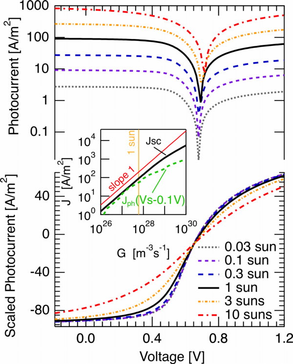 Today, I would like to extend these statements to the photocurrent in somewhat more general terms.
The figure to the right contains the simulated photocurrent for a bulk heterojunction solar cell of 100nm thickness at room temperature. Parameters were chosen according to typical experimentally determined values for P3HT:PCBM solar cells: Bimolecular Langevin recombination with a reduction factor of 0.1 and electron and hole mobility of 10-4m2/Vs were assumed (is it possible I never discussed this reduction really? Seems so, just mentioned it with references here). The top graph shows the photocurrent, in the lower graph the photocurrent was divided by the illumination density in terms of suns (thus, the current densities given on the y-axis are only correct for 1 sun). Consequently, if the photocurrent scales linearly with the light intensity, all curves should coincide. Let me remind you that this was interpreted by different groups (Street et al. among them, but not the first to follow this explanation) as a sign of first order recombination.
For up to one sun, however, despite the fact that only bimolecular recombination is considered, the photocurrent does not clearly deviate from the linear scaling. Slightly above one sun, a deviation becomes apparent for the photocurrent close to the quasi flatband voltage (or the point of optimum symmetry, if you like [Ooi 2008,Limpinsel 2010]. This can also be seen in the inset. The short circuit current deviates even later.
The reason for these difficulties to pinpoint the bimolecular recombination mechanism just by looking at the photocurrent becomes a little clearer when considering the relative charge carrier losses. In the figure to the right, the illumination density is now on the log x-axis, the reduction factor was varied (different traces). For the typical 0.1 Langevin reduction factor, a charge carrier loss of 10% is only seen at about 10 suns; the corresponding slope of the short circuit current vs. light intensity plot corresponds to 0.9 at this point (where 1 is classically interpreted as meaning 1st order recombination (some would say monomolecular), and 0.5 second order (… bimolecular)). The losses have to go to around 30% until the slope becomes 0.75. For the parameters considered, this jsc vs generation rate slope actually never goes to 0.5, despite the present bimolecular recombination. Thus, in analogy to the previous post, the point is that even from the light intensity dependence of the photocurrent it is very difficult for many typical conditions to unambiguously determine the dominant loss mechanism.
If you want to know the juicy details, read on here. It is a comment to a recent paper of Bob [Street 2010], which I sent to him before submitting it. I was very positively surprised to see him answer within a day, in a very polite and openminded way! [Update 2.11.2010] Our comment and the reply of Street are now online!
As a small bonmot, and to point out that I changed the definitions I use describing recombination as compared to an older post, where I quoted from [Kwan-Chi Kao 2004 (Book)]
The recombination that involves one free carrier at a time, such as indirect revombination through a recombination center (e.g., an electron captures by a recombination center and then recombined with a hole, each process involving only one carrier), is generally referred to as monomolecular recombination.
Now, following the definition typically used by physical chemists (as far as I know), I state that a bimolecular loss process is one where two nongeminate particles recombine. In case that one type of them is much more abundant than the other, for instance because of being trapped, this process may become a first order process instead of the second order process if the concentrations are similar. Nevertheless, I find it more logical (though longer) and more precise to call this process a (of decay) instead of monomolecular recombination. In constrast, I use the latter only for geminate recombination processes. Nevertheless, this distinction is a matter of opinion only. In different books or articles, you’ll find both terms for the same, so beware.

Carsten, thank you for these thought-provoking updates. A quick question for you: whenever I did light-intensity dependent I-V measurements, I found very frequently that the ratio of the short-circuit current to the light intensity, i.e. the so-called responsivity, appears to diverge at low light intensities. I was wondering whether you’ve ever observed something like this, and also whether you think this could be physically significant. I have not done enough research whether inorganic solar cells exhibit the same trend.
Good question, I am not perfectly sure! I imagine that such a deviation could occur for light intensities in which the concentration of photogenerated charge carriers is smaller than the concentration of dark carriers. The dark carrier concentration could for instance be influenced by doping due to oxygen exposure. Tell me in case you find this idea sane enough to consider and check it;-)
Dear Deibel,
I have read almost all of your archives about BHJ organic solar cells and I found it is so helpful (from your discussion on the archives, I have learned something i am not able to acquire from papers:) )..
I have a question: you question Street’s paper by simulaiton first figure in this achieve. From your simulaiton, it is clear that even for bimolecular recombination, all curve concide.
I am wondering, is that because at short circuit, dJ/dV=0, which means around short circuit, I-V curve is flat. Therefore, at Isc, extraction is sufficient (n,p in the device is very small) and recombinaiton, whatever bimolecular or monomolecular, is neglegible. The slope is 1 between log(Jph) and log( I) because no recombination, only extraction and extraction is monomolecular form. I am wondering, if dJ/dv is not zero at Isc (at short circuit, extraction is not so efficient), there will be recombination and Street’s claim in PRB 2010 could be right.
Dear Chris, thanks for your kind comment and the question. However, I am not sure if I understand the latter perfectly well, so please tell if my answer is not to the point.
For bimolecular recombination (BR), the photocurrent curves coincide for “normal conditions”, i.e. 1 sun or less illumination (although slight deviations are already seen) and typical recombination conditions. For higher illumination densities or thicker cells, the photocurrent will show the bimolecular signature more clearly — in case BR is the loss mechanism — and the Hecht equation as given by Street et al cannot be fitted to the data any more. For 1st order recombination, whatever the reason, and also for no or weak recombination of any kind, the slope d(ln(Jph))/d(ln(Plight)) is always one.
If you consider instead the voltage dependence, for 1st order recombination the Hecht equation seems pretty capable of fitting the photocurrent (but you can also fit it to cases where the recombination is low — any type — or off; just mu tau does not have any real meaning then). For sufficiently low recombination, the extraction length dc > film thickness d will usually imply that almost all charges are extracted. Thus, indeed, dJ/dV will be zero at short circuit – if the polaron pair dissociation is not (or only weakly) voltage dependent, and there is no minor shunt in the device. The latter is certainly unlikely. The former is a first order process, but it is a geminate recombination: certainly possible.
So what to make of this? Let’s wrap up. The light intensity dependence shows slope 1, but that does not mean much under the measurement conditions (< 0.3 suns, thin devices). dJ/dV is certainly nonzero, which is the sign for recombination (or shunt), but does not tell us whether that is 1st order or second order nongeminate recombination, or even geminate recombination. Again, you cannot tell just from the photocurrent curves alone.
Concerning my comment: my point was just to show that the steady state techniques used by Street et al. do not make it easy to distinguish between 1st order and second order recombination under the measurement conditions used. Instead, I was taking up the cudgels on behalf of transient techniques;-) My point was not to rule out 1st order recombination for the material system studied. With PCPDTBT-based devices, I do not have much experience. I do not believe that there will be monomolecular nongeminate recombination, I do believe there will be bimolecular recombination, but I do not know (in contrast, for P3HT:PCBM I do know that BR is dominant!). I am just pretty sure that different measurement techniques should be used to investigate the recombination mechanism.
HTH. Carsten
Dear Deibel,
I have three questions about your electrical modeling of organic solar cells (OSCs). Hope those won’t bother you.
1. According to most papers of OSCs, the Voc just depends on the difference of LUMO(acceptor) and HOMO(donor). But based on my modeling experience of “inorganic” solar cells, the Voc will depend on the “band barriers” of conduction band and valence band for heterojunction. Although the bimolecular recombination also controls the point of Voc, the band barrier still dominates.
Would you please make some comments on that difference of Voc mechanism between inorganic and organic solar cells.
For OPV:
Band barrier for conduction band: LUMO(donor)-LUMO(acceptor)
Band Barrier for valence band: HOMO(acceptor)-HOMO(donor)
2. In your simulation, do you consider the heterojunction effects? Or just simplify your model into “HOMOJUNCTION” with effective materials?
3. Do you have to set the carrier concentration of donor(p-type) and acceptor(n-type)? Would you please give me rough numbers as reference?
I really appreciate you spend much time establishing this fruitful discussion panel, which helps me fast broaden my organic material knowledge.
In fact, even though I’m interested in electrical working mechanism of organic solar cells, I can’t learn those knowledge efficiently since our group is focusing on nanostrcuture fabrication for “inorganic” solar cells.
(http://www.ieo.nctu.edu.tw/gpl/mainForEnglish.php)I hope you don’t mind putting the link here.:P
Anyway, really thanks for your kind patience.
(p.s. I also think the bimolecular recombination dominate the recombination mechanisms in OSC system, since inorganic solar cells have similar properties.)
Mark
Dear Mark, thanks for your email! Brief answers for now.
1 (Voc) The maximum Voc depends on the effective bandgap, which is indeed very close to the LUMO(A)-HOMO(D) gap. This value is reduced by band bending in the bulk as well as the injection barriers. Band bending is proportional to the steady state carrier concentration, which can be increased by photogeneration and decreased by recombination. Thus far, similar to inorganics. A difference is in the answer to
2 (junction): we simulate the bulk heterojunction as an effective medium, as we have a one-dimensional simulation. If you want to approximate the distributed heterojunction, you need at least a 2D simulation. The effective medium approach works pretty well, only thing missing is that for large phase donor-acceptor separation, the local band bending is neglected in our 1D approach. What are we missing with that? The local band bending can partly compensate for effects reducing the Voc. The extreme case is the bilayer solar cell, for which you can increase the injection barriers a lot without decreasing Voc… the latter is compensated by the band bending at the planar D-A heterojunction. In large phase separated bulk heterojunctions, this effect will be weaker, and therefore we do not consider it.
3 (concentration): the organics we work with are usually semiconductors or even insulators. Mostly, everything can be well described if you consider zero doping. Thus charges come from injection (thermionic emission model with maybe 0.1eV injection barriers or so at anode and cathode) and photogeneration (generation rate of around . So, open for discussion:-)
Best, Carsten
Dear Mr. Carsten,
Your blog is highly useful and extremely appreciable. I am a student from India who started learning organic solar cells two months ago.
I have a doubt which might seem very silly to a scientist like you. But I would be greatful if you can help me.
How to find the interfacial energy gap ( HOMO(A) – LUMO (D) ) practically?
Hope I am not bothering you..
Thankyou
Katie :)
Hi Katie, thanks:) Energy levels are not an easy topic, there is a lot of controversy already in the naming. Essentially what can be measured are only the charged molecular orbitals. The most reliable method is photoemission spectroscopy. For application on organic semiconductors, see [Deibel 2010] and [Guan 2010]. The latter is on a blend and thus more relevant to your question. Nevertheless, photoemission spectroscopy is about energy levels occupied with single particles, electrons OR holes. Cyclovoltammetry measures the same levels but is less reliable.
However, you are probably more interested in finding the maximum of the open circuit voltage. Here, you could determine Voc(T) and extrapolate to 0K, as done in [Vandewal 2010] or [Rauh 2011]. This measurement determines the effective bandgap which goes into the equation for the open circuit voltage [Cheyns 2008]. This equation and the measurements given are directly about the effective bandgap. The actual HOMO(A)-LUMO(D) gap, as determined by the single-particle energies as mentioned above, is actually larger. It was used by [Scharber 2006] as upper limit for Voc (q Voc = HOMO(A)-LUMO(D) – 0.3 eV), but that is rather an empirical relation.
Best, Carsten
Thankyou Mr. Carsten :)
Dear Dr. Deibel,
Thank you so much for maintaining this excellent blog – it’s a great resource for all of us in the OPV community and beyond.
I have a few questions about the use of the Hecht formula.
My understanding is this expression models the ratio of generated charges collected at the electrodes to those lost to trapping. Thus, this formalism was originally conceived as describing a system where trap-assisted (monomolecular) recombination dominates. I’m not clear however, whether the lifetime (tau) is supposed to be the “sweep-out” time for a generated charge or rather the effective time for a “free” charge to be trapped.
Furthermore, as you point out in response to Street’s work and in a comment above, it seems the Hecht formula can also accurately describe the JV characteristics of a system that is NOT limited by trapping. It is even less clear to me what the significance of tau would be in that case. For instance, in your very recent work outlining the OTRACE technique (http://onlinelibrary.wiley.com/doi/10.1002/adma.201200874/abstract) you measure an “effective lifetime” and use it as input into the Hecht formula. In this case, would it be correct to interpret this “effective lifetime” as the average time until a free charge recombines bimolecularly? Also, I’m curious if you were able to use your OTRACE measured lifetimes and the Hecht expression to model the field dependence of the photocurrent in your devices.
Finally, do you know where I could find an English version of Hecht’s original work?
Thank you!
Chris
Hi Chris, thanks for your comment. Just before my vacation, so my answer will be brief.
Hecht investigated AgCl crystals, and while he does not go into detail concerning the recombination mechanism, the lifetime in his equations does refer to the lifetime of charge carriers before being lost for the photocurrent (by recombination or trapping, although not stated by Hecht, AFAIK). This lifetime does not depend on the carrier concentration, meaning 1st order recombination, indeed what you call monomolecular.
For a more general treatment, you need to consider an effective lifetime depending on the carrier concentration. This is also what is often found in the OPV literature, e.g. by the Durrant group or by us: the parameter , with an effective (=nonspecific) recombination rate
  . Your interpretation as effective lifetime before nongeminate recombination occurs is correct. We have not tried to reconstruct the photocurrent vs voltage yet with our OTRACE technique, but it is on our agenda.
Do not know a translation of Hecht’s work, although I believe the most important part of his work is his equation, and there is not much additional or surprising information on it in his work.
My regards, Carsten
Carsten,
Thanks for the response. I think I have a better understanding now.
Enjoy your vacation!
Chris