
The last two times I wrote about transport resistance as a voltage-loss (or, depending on how you like to look at it, current-loss) mechanism in organic solar cells – in 2022 and 2025 – I mostly talked about fill factor: how a low active-layer conductivity bends the illuminated 

 This time I want to show you that a plot that is very common in today’s literature does not make much sense for today’s high-efficiency organic solar cells. I am talking about the plot of photocurrent – the difference between illuminated and dark current of a solar cell – vs what is called “effective voltage”, i.e.,

If you look at the current–voltage characteristics of state-of-the-art organic solar cells, as shown in the plot below, you can observe that dark and illuminated 


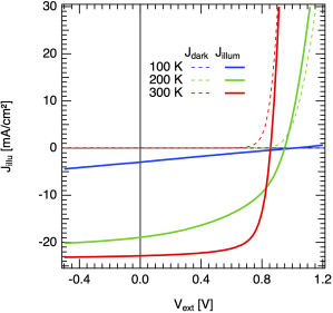
So, the question I hear you asking: why do the experimental dark and illuminated current densities cross?
For the field of organic photovoltaics, this question was first addressed by the Blom group, in Mihailetchi 2004. At this time, organic solar cells reached power conversion efficiencies of only 2 or 3%. So, Valentin Mihailetchi plotted the photocurrent density of a PPV:PCBM organic solar cell, 


“The photocurrent in conjugated polymer-fullerene blends is dominated by the dissociation efficiency of bound electron-hole pairs at the donor–acceptor interface. A model based on Onsager’s theory of geminate charge recombination explains the observed field and temperature dependence of the photocurrent in PPV:PCBM blends. At room temperature only 60% of the generated bound electron-hole pairs are dissociated and contribute to the short-circuit current.”
Continue reading “Return of the transport resistance: what Jphoto vs. Veff really tells you”

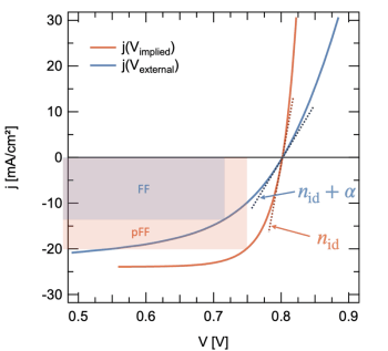
 . The result could look like the scheme shown in the figure below. I have adapted this figure from Maria’s new publication on transport resistance losses in organic solar cells [
 curve (blue) is the normal JV curve under illumination, where
  is the applied voltage. The down-shifted suns-Voc curve corresponds to the
  (red); the implied voltage is the voltage without any series-resistance imposed drops. In other words, the externally applied voltage drops over the diode and all series resistances, the external series resistance as well as the transport resistance that comes from a low active layer (or transport layer) conductivity. The implied voltage, as measured by the open-circuit voltage (at zero current, where series resistances do not play a role), corresponds to the voltage without drops over series and transport resistance.
  If a solar cell has a low active layer conductivity and is transport resistance limited, than the measurement of the suns-Voc curve to construct the