
Ideally, tandem solar cell made of a series connection of two subcells work as follows. 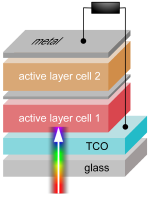 Both sub cells generate their own photocurrent by absorbing light and generating charges (as described for single layer cells in here), and have their own open-circuit voltage. Of course, as the two cells are connected in series, they influence each other. The photogenerated holes of cell 1 are extracted by the ITO, but where to the electrons go? They have to recombine with photogenerated holes from cell 2: that is what the intermediate recombination layer is for. If the photocurrent of sub cells 1 and 2 is initially unbalanced, the electric field is redistributed, such that the photocurrent becomes balanced… at a lower value, approximately determined by the worse of the two cells. The open-circuit voltage is aproximately the sum of both sub cells’ open circuit voltages. Of course, in cases of field redistribution, that does not quite hold true. So, what approximately happens in a tandem solar cell of subcells 1 and 2:
- open circuit voltage Voc = Voc1 + Voc2
- short circuit current Isc = min(Isc1, Isc2)
- fill factor is more difficult, but as a rough guide lets stick to the minimum of both as well
So for an ideal tandem solar cell, complementary absorption ranges, and balanced photocurrents are needed.
Recently, Kim et al. presented 6.5% efficient organic tandem solar cells [Kim 2007]. The samples were made of two series connected sub cells of polymer:fullerene blends. The anode was indium tin oxide on a glass substrate. The top cell (in terms of incident light) was PCPDTBT:PC60BM, the recombination layer was of TiOx and a special PEDOT:PSS, and the bottom cell P3HT:PC70M. The cathode was made of TiOx and Aluminum. The absorption ranges of these two material combinations complement each other quite nicely. By adjusting the thickness of the two sub cells, the photocurrent was balanced in order to get a high resulting photocurrent.
Only a short time later, Dennler et al. [Dennler 2007] presented optical simulations by considering thin film interference effects using a transfer matrix algorithm (and another one).  They verify that Kim et al. indeed used an advantageous thickness combination for both subcells (approx. 180 and 130nm) in order to optimise the photocurrent by balancing it. They continue to consider other thickness combinations with balanced photocurrent, and find higher charge carrier generation rates by increasing the thickness of both cells. Finally, Dennler et al. claim that by going as far as 565nm for the P3HT based cell, and 225nm for the PCPDTBT based sub cell, the efficiency can be as high as 9% power conversion efficiency.
I would like to comment on the last claim. In my humble opinion, one detail is neglected which is worth to be looked at more closely. The authors essentially calculate the energy dissipation in the tandem solar cell, and convert all the energy into photocurrent. This assumption becomes worse the thicker the active layer becomes. As I have pointed out in a previous post, the separation of Coulomb bound polaron pairs is strongly field dependent, one needs a rather high electric field in order to efficiently dissociate the pairs into free charges. The effective field in the active layer is (external voltage minus built in potential) / thickness. If the two voltages remain the same, and the thickness is increased (here from approx. 300nm to almost 800nm), the field decreases accordingly (by factor 2.5 or so!). Now as photocurrent is only generated by free charges, the photocurrent decreases significantly. That means even though the generation of excitons is much higher for the two thicker sub cells as calculated by Dennler et al., the charge generation will not increase in linear proportion, as assumed in the paper. Actually, I reckon that the power conversion efficiency will not exceed the one of the “thin” tandem device. Of course, there is no exact theory yet to consider the field dependence of the polaron pair dissociation realistically, but in order to not generate unrealistic expectations using “extrapolation by simulation”, a short note by the authors concerning the shortcomings of their model would be appropriate.
