
In the beginning 90s, a novel concept was introduced, accounting for the low exciton diffusion length in disordered organic semiconductors, as well as the required  thickness for a sufficient light absorption: the so-called bulk heterojunction solar cell [Heeger 1995]. This approach features a distributed junction between donor and acceptor material: both components interpenetrate one another, so that the interface between them is not planar any more, but spatially distributed. It is implemented by spincoating a polymer:fullerene blend, or by coevaporation of conjugated molecules. Bulk heterojunctions have the advantege of being able to dissociate excitons very efficiently over the whole extent of the solar cell, and thus generating polaron pairs anywhere in the film. The disadvantage is that it is somewhat more difficult to separate these polaron pairs due to the increased disorder, or that percolation to the contacts is not always given in the disordered material mixtures. Also, it is more likely that trapped charge carriers recombine with mobile ones. However, the positive effects outweigh the negative.
The most important processes of generation and recombination in disordered organic solar cells are shown in the figure. Excitons are photogenerated, diffuse to a donor-acceptor junction and 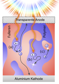 dissociate to polaron pairs (a) or recombine radiatively (b). If polaron pairs are generated, they can be also separated, now with help of an external electric field; the then free polarons can hop to the corresponding electrodes to generate a photocurrent (a) or recombine with other mobile or trapped charges (c). For an efficient bulk heterojunction solar cell, a good control of the morphology is very important. Rather simple methods of optimisation have been successfully performed only in the new millenium. The choice of solvent [Shaheen 2001] as well as the annealing of the solution processed polymer:fullerene solar cells [Padinger 2003] both lead to a more favourable inner structure in view of polaron pair dissociation and charge transport. Thus, the power conversion efficiency was increased manyfold, in case of the annealing from a bare half percent to above 3 percent. Might not be much, but the steep increase shows the potential. Indeed, optimisation by novel routes is a continuing process. Coevaporated Copper Phthalocyanine / Fullerene solar cells have reached 5.0% efficiency [Xue 2005], and solution processed polythiophene:fullerene cells even 5.8% [Peet 2007].
Next time, we’ll be looking a bit closer into advanced device architectures. Stay tuned;-)

Hi Carsten, I have read much of your blog and find it very interesting – you do a great job at explaining some of the more complex processes in OSCs. I have a quick question for you which may help me an others understand some more about how they work and the important processes involved:
How do you measure the exciton diffusion length and what is theoretical basis for such a measurement?
Hi! Not much time now, so only references: more maybe another time;-)
[Kurrle 2008] Determination of exciton diffusion length on an organic crystal. Better even is to combine this method with an optical model (transfer matrix algorithm or so)
[Ineverwantedtobeasciencistiwantedtobealumberjack 2010] 27nm for P3HT, wow, probably only possible for the optimised synthesis routes, because earlier measurements gave much lower values, such as 8nm in [Shaw 2008]. If not for a long exciton diffusion length, however, Alex would not have had success with his solution processed bilayer [Ayzner 2009]. Regards, C
P.S. from Bittner group? only temporarily? Forgive my (potential) indiscretion, just curiosity;)
I read the Ayzner 2009 paper and thought it was really good. Would have liked to have seen some EQE spectra though
Quite so, but less for proving the efficiency as for seeing how a bilayer behaves. The results or Alex are really striking, and–including the supporting information with SEM cross sections–pretty convincing. Still, I discussed with him quite a bit, because I have not stopped wondering why it works so well!
Hi,
Thanks for the references! – from a first look I think they will be very useful. I did a quick literature search on the topic already and surprisingly I did not find some of these papers, thanks for sending me in the right direction.
Your curiosity :) was very close, although I am not in the Bittner Group, I am an Irish graduate student based in Houston doing some work on organic solar cells.
Thanks again,
Nigel
My pleasure! Don’t hesitate to come back for discussion, Nigel. Best wishes, in particular for your research on exciton diffusion, Carsten
Carsten,i beneift a lot form your bolg,thank you very much!I like those pictures in this topic,i want to know if i can use them in my presentation?of course i’ll indicate the copyright. Linda
You are welcome to use them, Linda. Cheers, Carsten
Hi Carsten
I’m not sure if this is a stupid question. The maximum power output of a solar cell is always given as the point where the product P=I_mpp V_mpp is maximum in the fouth quadrant. But of course there are also positions in the third quadrant when this product is greater (e.g. at V=-V_mpp,I=-I_sc). What are therefore the secondary (aside from maximizing P) considerations that go into choosing the operating bias for solar cells.
Thanks!
Richard
Hi Richard, you need to make the product of I and V at the same voltage (or did I misunderstand you? Your example was -Vmpp for the voltage and at 0V (sc) for the current). Thus, if you have an I(V) vs V curve and plot P=I(V)xV vs V, you get only one maximum (actually minimum, a power you can “extract”): at the maximum power point, which is always in the fourth quadrant. Best, Carsten
Dear DEIBEL,
Just to say thank you very much for this blog. It is very very… useful.
Arouna
Hi.
I am new..but it is very interesting.
I have a question, if you can help me.
Do you know a mathematicl model for the energy yield of organic photovoltaic cells???
Many thanks
Hi. Your question is too unspecific, sorry. C
I know I’m late to the party, but I just wanted to comment on the beginnings of this thread. Being the Ayzner guy mentioned above, I feel justified weighing in. :)
When we first wrote the paper, we did believe that the exciton diffusion of P3HT could likely be made significantly longer then in blended BHJs by processing P3HT and PCBM sequentially from orthogonal solvents. This was based on our thinking that there was little PCBM penetration of the bottom P3HT layer. Our understanding of this system has since evolved, and we believe (as multiple groups including us have reported) that there is significant interdiffusion of PCBM that occurs upon deposition of the fullerene overlayer.
Nevertheless, the P3HT is indeed more ordered in the as-cast (quasi)bilayer film than if one had just cast a film from a blend solution. We do think this likely improves the EDL, consistent with a report by a group from Japan using ultrafast exciton-exciton annihilation measurements on neat P3HT films.
Carsten, thank you for all your conversations on the topic. Hope all is well.
Dear Alex, thanks for your post! All is well, presently at the SimOEP conference in Oliva, Spain – excellent weather, but my talk is coming up in two hours… Best wishes, and hope to meet you soon at the next conference! Carsten
Dear Dr Diebel,
I’ve been a follower of your blog for some time now. I am impressed with the image quality and would like to use them in my phd thesis. I wonder how I should approach copyright in this case. Would it be fine to use the images with credit given as (image courtesy of Dr. C. Deibel: http://blog.disorderedmatter.eu)?
Hi Colin, thanks. Usually that is fine, although some of the figures are also found in our (review) papers, e.g. in the [2010 review], which could be credited alternatively. The advantage is that the figures are vector graphics, not bitmaps as on this blog. You could have a look on my [arXiv page]: if you choose “Download => other formats”, you can get the latex source files and pdf figures in high quality. Success for your thesis, Carsten
Why electrons are collected in cathode and holes on anode in organic solar cells?
Because the gradients in the corresponding quasi Fermi levels point in these directions. These gradients will usually manifest in contributions of both drift and diffusion. I believe there is some discussion on this in the photovoltaics book by Peter Würfel, where it is shown that in principle, a solar cell could function only based on diffusion. How good such a solar cell would be is another question;-)