
As an in-between, we’ll talk about a topic which will hopefully become more and more recognised by the organic photvoltaics community: the shortcomings of the established Shockley model, 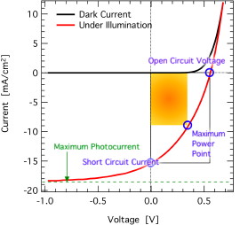 made for crystalline inorganic diodes, when applied on fitting organic solar cells.
The most important figures of merit describing the performance of a solar cell are the open circuit voltage, the short circuit current, the fill factor and the (power conversion) efficiency. The fill factor is given by the quotient of maximum power (yellow rectangle in the figure) and the product of open circuit voltage and short circuit current (white rectangle); it therefore decribes the “squareness” of the solar cell’s current-voltage characteristics. The efficiency is the ratio of maximum power to incident radiant power – typically radiated by the sun. E.g., a well-known detailed balance calculation for inorganic single gap solar cells gives a theoretical maximum of about 30% power conversion efficiency [Shockley 1961]. The upper limit for organic solar cells is somewhat lower, but that’s another story.
As you may know, the Shockley diode equation
![]()
(which is older than 1961 but also used in the paper) looks as in the equation below when corrected for real inorganic devices with series and shunt resistance:
![]()
In the Shockley equation for “real” diodes, an optional photocurrent is included by a parallel shift of the current-voltage curve down the current axis: this is the (constant) photocurrent jph. Now, many people have fitted the current-voltage characteristics of organic solar cells under illumination with this equation, but as one can clearly see from the figure above, the shown j(V) curve for a typical organic solar cells has a strongly field dependent photocurrent. There is for example a crossing point of dark and illuminated curve at approx. 700mV which cannot be explained by the Shockley equation. The reason is, as explained in “How Do Organic Solar Cells Function? – Part One“, that the Coulomb bound polaron pairs (approximately: electron-hole pairs) have to be split by the externally applied electric field. At 700mV (in this instance), however, the internal electric field, which is the contact potential difference minus the external electric field, is zero. That means flat band conditions, and therefore there is not enough driving force for the polaron pairs to be separated: there has to be a crossing point. (Actually, even in inorganic compound semiconductors such as CuInSe2 there are similar crossing points, but their origin is different.)
As you can also see from the upper 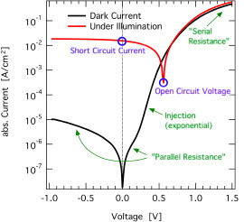 figure, it sometimes happens that the maximum photocurrent is not reached at 0 Volts, i.e., under short circuit conditions, but only at more negative bias, corresponding to a higher internal field. This happens in organic solar cells where the polaron pair dissociation is more difficult, e.g. if the active layer is thicker, and therefore at the same (external) voltage the (internal) field at zero bias is lower.
The details of polaron pair dissociation are not completely understood. Right now, the so called Onsager theory [Onsager 1938] and its somewhat more modern incarnation [Braun 1984] are used to describe its field dependence. According to me, however, the last word is not yet spoken… which might not mean much;-)
Coming back to the Shockley equation. A positive bias leads to the injection of charge carriers into the solar cell: the current increases exponentially, we see a rectifying (=diode-like) behaviour in the ideal case. In real solar cells, however, there are losses, considered in the second equation above by two resistors. The so called series resistance Rs – in series with the diode – describes (amongst others) contact resistances such as injection barriers and sheet resistances. In contrast, the parallel resistance covers the influence of local shunts (=short circuits) between the two electrodes, i.e., additional current paths circumventing the diode.  Works nicely in silicon solar cells, but in organic solar cells some problems appear: the “parallel resistance” now seems to depend on the voltage and illumination intensity, the “series resistance” also also changes with voltage.
Unfortunately, there is no analytic equation yet to properly describe the peculiarities of organic solar cells. what we’ll settle for now is to describe the known differences between Shockley and real organic cells. As organic semiconductors are usually not as conductive as their inorganic counterparts, at higher voltages (and sometimes also at higher negative internal fields under illumination, even in the 4th quadrant!) space charges can build up, leading to space charge limited currents. Here, the current is proportional to the square of the voltage (an not linearly proportional to the voltage as for resistors). (Actually, in organics, the well-known Childs law or Mott-Gurney law with j being proportional to V2 is also not strictly correct… maybe more on this another time;-) This can lead to the determination of apparently voltage dependent resistors. As mentioned above, space charges under illumination, which can be induced for instance by trapped charges, can superimpose with the “parallel resistance”, which than becomes voltage (and light) dependent as well. And of course, shunts and contact resistances do also exist in organic solar cells.

I like the graphics for the I-V curves you used. Did you make them yourself or do you know where you found them. Thanks.
Thanks for your comment. All images are self-made, of course:-) I’ll email you a pdf. If you use them, I’d be grateful for a citation. Regards, Carsten
Let me congratulate you on this excellent blog. Like Chris said on 19th July it is so helpful… we learn things we are not able to acquire from papers.
I would like to ask two rather unprofound questions: first concerning your Current-Voltage characteristics of OSCs. Why is the behavior of the dark current in a general OSC so similar to a Si:c pn junction? Here the concentration gradient from p to n of the available charges allows for a (exponential) positive current as soon as a positive ext voltage lowers the internal potential that exists at equilibrium. The charges themselves are available since kT is of the same order of the ionization energy of the dopants. In a dark OSC, it seems to me you have no available free charges for transport (even after doping). But you mentioned in your note Polaron,…,Exciplex: ”Singlet and triplet excitons can also be formed due to interaction following charge injection…”. Is it possible that charges injected externally into the OSC (in opposite sense to the photocurrent that would flow under illumination) will somehow generate excitons (in a reversal of the dissociation mechanism exciton to Polaron Pair)? This being the case the more you lower the internal electrostatic field the less dissociation of excitons would take place (contributing to oppose the injected current) and a positive current charge carrier might hop from molecule to molecule… would there be radiative photoluminescence then?
Second (even more boring) question: concerning this figure of 1,3 Kw/m2 of radiation on a 500km orbit satellite (ACRIM program). It seems to me that if you resort to a pyrheliometer you are basically interpreting the power of radiation (irradiance) as a heating power. Since photons transmit chemical energy and brightness (illuminance) in addition to heating a surface, probably there will be far less photons reaching a unit surface (photon flux) than calculated in this way…
Carlos, thanks:)
In the dark, you do have free charges available in an organic semiconductor device, no matter if made of one semiconductor (e.g., LED) or two (a solar cell). Usually, these carriers are not intrinsic, but injected. If you can inject both electrons and holes, you may have a certain fraction of them interacting, generating excitons (singlet excitons and CT singlet excitons for diode and solar cell, respectively). The latter may recombine, also radiatively. This is the basis for organic light emitting diodes, where the resulting emission is significant. For solar cells, you will also have radiative recombination, but that cannot be seen by eye only, you will probably need a good detector;-) This emission is called electroluminescence, as it results from injection, not photoexcitation.
Concerning radiation, I do not think that you will have a (significant) discrepancy between the “thermodynamic” measurement and the photon flux on the solar cell surface. Solar irradiation is based on a distribution of photon energies, thus a spectral distribution, with a certain flux depending on the photon energy. For solar irradiation, black body radiation of 5000K or so works pretty well, therefore your detector does not need to measure every part of the spectral range separately. Best, Carsten
Thank you, for your prompt answer which I thought I would be notified of by wordpress.com or other but only now by chance did I discover it.
Sorry to insist: why is the dark current in the OSC, in reverse bias, which increases the internal field, so low, then? … which is the same thing as asking why does the non-illuminated device act as a rectifier.
Best wishes,
Carlos
About my last question, you would probably mention the Schottky barrier.
If you do have the time to come again on the Child’s law (J~ V1.5), could you please comment on:”[…]exponent larger than 2, which is commonly explained by transport with an exponential distribution of traps[…]”, from a paper on trimolecular recombination that mentions your work, by Schubert, M., Steyrleuthner, R., Bange, S., Sellinger, A., Neher, D., Charge transport and recombination in bulk heterojunction solar cells containing a dicyanoimidazole-based acceptor, Phys. Status Solidi A 206, n.º12, 2743-2749 (2009)?
Best wishes,
Carlos
There is rectification in the dark solar cell, because it is an ambipolar device with asymmetric injection barriers. In forward bias, electrons and holes are injected (from anode resp cathode), in reverse bias the corresponding injection barriers are too high: electrons (holes) cannot easily enter at the cathode (anode). Illumination gives you charge generation within the organic blend, thus generating an additional (negative/extraction) current, but the other boundary conditions remain the same.
Space charge limited currents (SCLC, with Child’s law as the trap-free case) is unrelated to recombination. For details, have a look at [Arkhipov 2001], in which the behaviour is well explained for gaussian DOS. The principle is the same for exponential DOS.
Best, C
First many thanks for keeping this blog, it has been very, very useful to me…
Just wanted to point out a paper from Durrant claiming that in some polymer cells current generation does not seem to be field dependant (they use Transient absorption techniques to compare different devices with very different J-V characteristics:|J. Phys. Chem. Lett. 2010, 1, 3306–3310).
I’m very new to this field and there are some things I don’t understand like the space charge concept. About space charge build up in organic solar cells (suposedly due to lower mobility and higher trap concentration, right?), is there any way to characterise such space charge? Some charge extraction experiements have been reported on polymer-based solar cells where the excess charge in the devices often follows an steep increase with light bias (suposedly exponential)(see:Shuttle et al. Appl.Phys LEtt.,93,183501, 2008; Shuttle et al. Appl.Phys Lett.,92,093311 (2008); Hamilton et al. J.Phys. Chem. Lett., 2010, 1, 1432). Is this charge build such “space charge build up”? From you paper, phys. stat. sol. (RRL), 2, 175 (2008), I understand that “efficient charge extraction at high mobility” limits Open circuit voltage, because there won’t be any charge build up and if mobility is too low charge build up will increase giving high VOC but low current. However some studies we are carrying up on small molecule (DPP(TBFu)2)-based BHJ devices (first described by N’Guyen et al.: adv. func. mater. 2009, 19, 3063) seem to show a different trend, as Open circuit voltage is very high (very close to theoretical values, and currents are very high). In contrast to reported devices the charge density show a complete linear dependance on light bias (no charge build up)! Could this mean that band bending in such devices is significant, then?
Hi Aurel, thanks!
Durrant et al are right: for many “good” organic solar cells at room temperature, the charge generation seems to be field independent. The same is seen by Street et al (PRB 2010, do not have the reference at hand). There are not that many studies on this field. We were able to model the photocurrent of P3HT:PCBM solar cells by a charge generation yield of 60% at short circuit and 50% under open circuit conditions, which is also almost field independent [Limpinsel 2010].
Space charge build up happens in low mobility materials in the (dark) injection regime (see my reference in the previous comment in this thread), and sometimes also in the photocurrent [Mihailetchi 2005] [Wagenpfahl 2010]. I do not think that the “charge buildup” seen by the Durrant group is similar, but have not checked their papers again to make sure.
Our phys stat sol RRL was made under the condition that even at high mobilities the recombination occurs with the Langevin recombination rate. This is not a very good assumption, I am sorry to say. Please find a more applicable simulation here [Wagenpfahl 2010a]. In any case, it is difficult to get into this high mobility regime with organic semiconductors. Concerning your studies, more important to Voc are probably the energy of the charge transfer complex (the “effective bandgap” or “maximum Voc”) which is, in view of Voc, reduced by charge carrier recombination. What do you mean with “charge buildup” in view of the linear Voc dependence on light intensity? The term does not quite fit here, it seems to me, more important is the recombination regime (1st order recombination or 2nd order, and even then it depends on the “strength” of the recombination”. Details on request;-) Best, C
I appreciate your courage to dwell in these matters in the circumstances…
I suppose anode (+) should be substituted for cathode (-) (or electrons by holes)…
When you have the time and had some sleep (according to my experience, things will get steadily worse from now on, until one reaches the IT summit…), referring to the denominator of mobility in CELIV, shouldn’t it be tmax2 in the Schubert et al. paper I mentioned previously, as in your paper Phys. Status Solidi A 206, No. 12, 2731–2736 (2009) ?
Thank you so much for the answer, your thoughts and the Arkhipov paper,
Congratulations, Good Luck and very
Best wishes
Carlos
Thanks for the good wishes! The definition of anode and cathode is not very specific, it seems to me, and depends also on the action (i.e. can be different for diode and solar cell, light generation vs current generation). Typically, the electrode with the lower work function is called anode in the papers about organic solar cells I know. Concerning the Schubert paper, I think they have a typo, but I am pretty sure they use the correct equation (including the correct tmax2) for data evaluation.
Hi Mr.Carsten
I hope that you’re fine.
please I would a summry about macroscopic simulation of I-V charactersic,for BHJ OPV.in other term if we use 1D DD model what are the main mecanisms and effects that one could be study. the same thing about 2D and 3D models.
best regards
Hi Khadidja, if you want to program a macroscopic simulation by yourself, I rather refer you to the excellent literature:
1d sims are excellent tools for testing the influence of a given model and its parameters on the IV characteristics and on carrier profiles, recombination rates etc. 2d and 3d sims need much more computer power, are often not necessary, but could be interesting to study an explicit phase separation (in contrast to the effective medium used in 1d) including the band bending at this explicitly defined, spatially distributed donor-acceptor heterointerface.
P.S. Pressed the wrong button previously, sorry.
Thank you, for your prompt answer and for the books that you have recommended me
best regards :)
Hi Deibel, thanks for your helpful blogs. I have a question about the dark current. Let’s take the Al/P3HT+PCBM/PEDOT:PSS/ITO system as the sample, can you explain in details how charge carriers are injected in dark under different polarities of bias? Thank you very much.
Hi! Not much time left, therefore let me refer you to inorganic semiconductor textbooks, which give a good approximation also for organic semiconductors in terms of injection: usually, the model of thermionic emission is applied to organic solar cells. Concerning band bending, see e.g. [Lange 2011], although this is for neat polymers. There is not much experimental work on injection itself, but concerning the role of disorder in the injection process, see e.g. [Wolf 1999] and its two followup papers.
Thank you very much for the references. I’ll read them. PS: I’m trying to understand the fundamental differences between the organic donor-acceptor solar cell and the inorganic p-n junction solar cell physics.
Hello Deibel,
it is becoming a clise but finaly a usefull blog that provides info on things people do not publish…..
i have some issues on J/V interpretation… i do not actually get what “rectification ratio” is. could you please spend some time and show it in a graph or explain it a bit more?
is built-in voltage (Vbi) the “theoretical maximum” Voc? is it defined by the WF of the electrodes? or by donor’s HOMO-acceptior’s LUMO?
can you actually use the following sentence “generated power in the 4th quartrant is consumed in order to overcome the extra barrier of the series resistance”? (for devices with high Rs)
how can you find saturation current from the J/V graph?
what about a post on ITO free devices?
Hi!
Rectification is abs(J(x)/J(-x)) for voltage x>0V, and thus is a figure of merit for diode rectification and shunt resistance.
Vbi (work function difference of electrodes, yes) is not the theoretical upper limit of Voc, as one can think of cases with Voc>Vbi, but IMHO it is practically a kind of limit for solar cells with high efficiency.
I did not get the Rs sentence, sorry. High Rs will reduce the power yu can get from your solar cell, yes.
Saturation current: highest absolute current under illumination in 3rd quadrant, if shunt is negligible.
I am not so much into engineering stuff, sorry, the tandems were an exception;-)
Best, C
P.S. Clise?
lol
that was a really misspelled cliché…
i think i still do not get…
“…In fact, no correlations of Voc with the optical gap of any of the blend constituents, as predicted by Shockley and Queisser6, are observed. Instead, Voc is found to scale with the difference between the highest occupied molecular orbital energy of the donor and the lowest unoccupied molecular orbital energy of the fullerene acceptor…” (On the origin of the open-circuit voltage of polymer–fullerene solar cells, Vandewal et al. Nature Materials)
BUT others say…
“…we have found that there is a linear correlation between Eg as determined from the onset of the photocurrent generated by CT absorption and the Voc of the solar cells. These findings go one step further than the widely accepted correlation of the open-circuit voltage with the LUMO(A) – HOMO(D) difference, as it is shown that our proposed correlation can also explain variations in Voc, observed for different preparation and aging conditions of the same polymer:PCBM material system…” (The Relation Between Open-Circuit Voltage and the Onset of Photocurrent Generation by Charge-Transfer Absorption in Polymer : Fullerene Bulk Heterojunction Solar Cells, Vandewal et al AFM)
When at the same time…..
“…Consequently, the built-in voltage can be read at the cross point between the exponential and SCLC regime, which amounts to Vbi = 1.28+/-0,02 V. This value can be taken as an upper limit for Voc in this device, but does not provide accurate information about the band bending at the LiF/Al-PCBM contact…” (Cathode dependence of the open-circuit voltage of polymer:fullerene bulk heterojunction solar cells, Mihailetchi et al. APL)
“…Controversially debated is also the correlation between Voc and the built-in field ( Vbi ), which is defined as the difference of the work functions of the metal contacts or doped charge-transport layers if present (including interface dipoles). Vbi is important for a well working solar cell, but not necessarily correlated with V oc , as we will show…” (Influence of Hole-Transport Layers and Donor Materials on Open-Circuit Voltage and Shape of I– V Curves of Organic Solar Cells, Tress et al, AFM)
Do we follow a pn junction model?? or the M-I-M one?
the only thing that i clearly get is that nobody actually knows 100% the Voc is coming from!!!
p.s. is there a way to upload a *.jpg in my comment?
p.s.1 while checking out some PEDOT:PSS i found out that there are Hole Injecting Layer and Hole Transporting Layer ….what is the difference?
sorry for all the trouble and time consumption….
Shockley and Queisser vs “BUT”: in inorganics, optical gap and effective gap coincide. This is not the case for (two-component) organic solar cells.
If you manage to stuff your solar cell with charges, e.g. by playing with the surface recombination velocity, you can go beyond Vbi AFAIK. Your photocurrent will be terribly low, though.
The MIM model is a special case in which the electrodes limit Voc, whereas usually the bulk limits Voc (by a combination of effective gap and recombination). See e.g. [Rauh 2011]: bulk limit at high temperature, electrode limit at low temperature (“MIM”).
Nobody knows 100% of anything;-) However, the open questions concern IMHO more the details of recombiantion mechanisms etc, and less MIM vs …
I am pretty sure there is not way to upload jpeg in comments; you could change your avatar though;-)
Wow…that was fast!! :)
Thanx Carsten!!
My pleasure:)
Hi Carsten
thanks for your helpful blogs
I would ask you about the dominant losses (recombination) that can effect J-V characteritcs (depending on the new reserch to investigate them in the drift diffusion model(1DD))
best regards
Hi Khadidja, mostly nongeminate recombination for state-of-the-art cells, but also geminate recombination. Charge surface recombination does not seem to play a significant role. Best, Carsten
thanks ;)
Carsten,
I just discovered this blog and I couldn’t be happier and thankful.
I have a request: could you send me some good reference (or explaining by yourself..) about understanding the dark IV plot? I still have some problems in getting it. For example, one of the things I don’t know is why my lowest current point doesn’t correspond to V=0, but to V<0.
Thanks a lot for any help you'll be able to give me
Hmmm, the scenario you describe sounds as if you have very low currents. In that case, and more pronounced for faster voltage sweep rate, you can get a hysteresis effect. Please check by measuring your current in sweeping the bias voltage from + to + and also vice versa. If you get symmetric zero crossings, once for positive and once for negative voltage, it will be this hysteresis effect. Slower voltage sweeping will usually help somewhat, but probably your major problem is that the film conductivity is too low. In general, the Shockley diode equation – extended by parallel and series resistance – will show you what to expect as I(V) curve of a diode or solar cell without (and, to some extend, with) illumination. Wikipedia may give you the first links, or come back here! Good luck for your solar cells and your research, Carsten
Hi Carsten,
First, thank you for your helpful blog and for your kind replies!
It has been stated elsewhere that Voc is linearly dependent on HOMO (D)/LUMO(A) deference in the case of Ohmic contacts. At the same time it is affected by illumination intensity and the type of electrode used. For example, at higher light intensity, the VOC increase because of the splitting quasi-Fermi levels due to the higher charge density. In another case, the use of Al/LiF in P3HT:PCBM PV blends has shown to increase the PV characteristics including Voc than the use of Al alone. The increases related to the charge extraction characteristics (low leakage) in the case of Al/LiF. But, this is contrary to previously indicated by one of the participant “efficient charge extraction or high mobility, limits Open circuit voltage”. So, my question is; how could I relate the gain in Voc with the improved extraction or charge mobility?
In another case, if low mobility favors Voc (it has been shown for cells measured at low temp.), why cells annealed at high temperature but measured at RT are showing higher Voc and Jsc (at the same time) as compared to non-annealed cells?
Thanks
Hi Selam! Well, indeed the Voc is usually linearly dependent on HOMO (donor)/LUMO(acceptor) difference. That is, the *maximum* possible Voc is approximately *equal* to that difference or to the energy related to the charge transfer complexes (see papers by Koen Vandewal, for instance). The actual Voc is lower that that maximum due to (1) recombination and (2) limitation due to the electrode work function difference. The first point, recombination (vs generation, which are equal at Voc by definition), will consist of radiative and nonradiative recombination, can occur at the surface and in the bulk, and does depend on the charge carrier concentration — and therefore also on the illumination intensity.
Concerning your example, “at higher light intensity, the VOC increase because of the splitting quasi-Fermi levels due to the higher charge density” is probably a solar cell which is not limited by the contacts, and instead is limited by recombination (1). The other case, “the use of Al/LiF in P3HT:PCBM PV blends has shown to increase the PV characteristics including Voc than the use of Al alone”, corresponds to (2): the work function difference was increased, therefore the solar cell is not contact limited anymore, but limited “only” by recombination.
Concerning “efficient charge extraction or high mobility, limits Open circuit voltage”, should be translated to something like high mobility increases recombination: with the Langevin prefactor being relevant for recombination between pairs of free as well as free with trapped charge carriers, higher mobility implies higher recombination rate, leading to lower open circuit voltage (and often higher short circuit currents due to better extraction;-).
Your final point is annealing. There, it depends on the details why Voc and jsc may increase or decrease (not everything gets better for all annealed devices;-), but the principle remains always the same: if contact limitation is not involved, than the ways to increase Voc are (a) increasing the maximum Voc, i.e. the HOMO-LUMO gap resp. the CT state energy (also, the effective gap), or (b) decreasing recombination. A morphology change, which is usually a prominent reason that annealing influences the device characteristics, can have an impact on both.
Best, Carsten
Hi Carsten,
Thank you so much ! It has helped a lot ! I have one more question, If there is contact limitation, how does the Voc determined (is it the difference of the work function of the two electrodes, or …?)
Selam
If you dont have an ‘ohmic’ contact then I think the maximum open circuit voltage becomes the difference in the metal electrodes (like a MIM device?). I think this is the case for instance with PFO blend devices, the deep HOMO at 5.8 EV does not make an ohmic contact with PEDOT or ITO, limiting Voc. You also have similar situations with single layer devices where the polymer does not form an ohmic contact with either the anode or cathode.
Indeed so. The Voc is given by the maximum energy two oppositely charged charges can have when being extracted. This energy is determined by the bulk material, and can be expressed as the splitting of the quasi Fermi levels for electrons and holes. However, the work function difference of the electrodes will limit the Voc if it is lower than the Fermi level splitting in the bulk. That means, the maximum possible Voc is given by bulk properties (the yield of photogeneration and losses by charge carrier recombination), but can be limited by space charges (s-shaped I(V)) and electrode work functions.
Actually regarding this part of device physics I always had many question, the biggest as: what is the origin of shunt resistance and diode quality in organic solar cells? So apart from the film quality problems, surface recombinations near the electrodes/buffer layers also directly lower the shunt resistance right? Does it have something to do with the internal nongeminate recombination of charge carriers? If yes then what determines the diode quality? And how can I relate the nongeminate recombination or dark current to diode quality and shunt resistance? And there should be some relation between nongeminate recombination and dark current right?
Hi Carsten, hope you are ok!
you have mentioned that higher mobility does not improve the power conversion efficiency significantly. in which post have made the details?
Best
Hi, that should be the one, Mobility and Efficiency of Polymer Solar Cells. It would be too simple to say that higher mobility does not help and depends on several factors. Most important, the higher the mobility the faster charge carriers can be extracted to avoid recombination. However, if a Langevin-like recombination (i.e., with the mobility in the prefactor) is active, the corresponding recombination rate will also increase. Going to really high mobilities, however, Langevin is not the right model any more. In addition, surface recombination does have some limited influence as well.
In a BHJ device, we talk about D-A junctions present through out the active layer. A junction should be present within the range of the exciton diffusion length. Considering this, we may say that the junctions are also this much far away from each other, say approx 20 nm. When we talk about energy band diagram between donor and acceptor material and how the exciton transfers, we consider an ideal case, but do the junctions at such close proximity to each other have an effect on the barrier formation and band diagram there, subsequently on charge separation?
Actually, it may be. [McMahon 2011] calculate the energetics of P3HT:PCBM blends. They state already in the abstract
Measurements on bilayer model systems also show an impact of the local molecular arrangement on energy levels and photogeneration yield, see e.g. [Rand 2012]. I am just heading back from the 223rd ECS meeting in Toronto, and Brendan O’Connor reported on indications that P3HT/PCBM bilayers, which were stretched treated differently by stretching yielding different predominant polymer chain orientations, lead to differences at the heterojunctions. Thus, for a finite donor-acceptor phase separation, the local morphology does seem to play a role for photogeneration.
I don’t disagree, but I would point out that none of the above results are dependent on wether the interface is bilayer or bulk.
Agreed.
I don’t think so. If I understand you correctly, if are you asking if the HOMO-LUMO energies of the donor and acceptor are dependent on the phase domain sizes, then in principle the answer is no as molecular energies are a property of the molecule (or more properly the chromophore) and remain unchanged regardless of environment.
Thanks all!! I somewhat get an idea from the discussion. @last reply, i actually meant the energy levels at the junction, and not the homo-lumo dependence of the materials on the domain size. @Dr. Deibel Thanks for giving the reference.
Hi,
I would like to use the I-V curve figure for my thesis to be published.
Is it your? Could I use? Of course with reference.
Thank you!
Francesca
Dear Francesca, my pleasure. You can get the originals on arXiv, http://arxiv.org/abs/1003.0359 : click “Other Formats” on the upper right and you can download a zip-file which also contains the original high-res images as pdf files. I should mention, though, that the images are published in that long review paper of mine, http://iopscience.iop.org/0034-4885/73/9/096401 , which is also the proper reference, so you should ask IOP for reprint permission. Usually, this is uncritical for a thesis, a review, etc. Best wishes, Carsten
I hope everything is going well with you.
if possible, would you please do me a favor and reply to my question.
how can extract the value of Voc, Isc, Vmpp, Impp in different irradiance in mfile matlab code?
THANK YOU
It is usually my pleasure to answer questions related to the blog topic here, to the extent of my knowledge. While I could answer your question, it is less a question about the physics of solar cells than a request to solve your “home work”. This I am not willing to do. If you come up with a related physical question, do ask.