
Where does one start after so long an absence — meaning only the blog abstinence; I have been working and publishing since last time;-)  One of the things which have been on my mind is the ideality factor, a figure of merit for the charge carrier recombination mechanism in a semiconductor diode. In short, a diode ideality factor of 1 is interpreted as direct recombination of electrons and holes across the bandgap. An ideality factor of 2 is interpreted as recombination through defects states, i.e. recombination centres. More on that in a later post, let’s start with the basics.
A couple of years ago, I wrote about some general properties of current-voltage characteristics of organic solar cells, but did not describe the ideality factor.1 I think the ideality factor was mentioned only once, and then without details.
The Shockley diode equation describes the current–voltage characteristics of a diode,
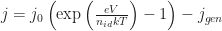
Here, 


The current
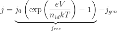
However, the term 


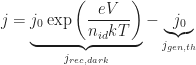
so that at negative voltages, 
 (Please note that under realistic conditions,
How can one determine the ideality factor and the dark saturation current (at least in principle, see below for a better way on real devices)? It is common to neglect the thermal generation current (the term -1, multiplied by 

so that the ideality factor can be determined from the inverse slope of the ln(current) at forward bias, and the dark saturation current from the current-axis offset. Let me already tell you that I do not recommend this approach, for reasons written below, and as explained in more detail in a recent paper of Kris Tvingstedt and myself [Tvingstedt/Deibel 2016].
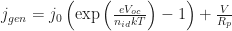
Under illumination and at open circuit conditions, 

which has the same shape as the Shockley equation in the dark. This means that if you measure (

Resistance
Even a very good real solar cell does not exactly follow the Shockley equation as stated at the beginning. Contact resistances and small shunt currents flowing from electrode to electrode in parallel to the diode (i.e. without rectification) have to be considered. These effects can be approximated by considering a series resistance 

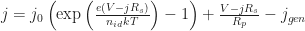
That means, the internal voltage at the solar cell is reduced by a voltage drop across the series resistance, and the diode current is essentially superpositioned on a shunt current. Here, indeed, the dark current in reverse voltage direction is not
If we again look at what happens for
the term 
 is “measured” without current flow, so the series resistance does not apply. (Note, although pretty evident I think: all figures in this post show calculated data, not measurements!) However, the shunt resistance still does! Nevertheless, this implies that while the ideality factor determination from the dark current–voltage characteristics under real conditions is limited by series and shunt resistance, the method using (


 Similarly, ideality factor should be determined with the (


So, what’s next. I plan to write two more posts on the ideality factor, one on its relation to the recombination rate, and one the transport resistance (see recent papers by [Würfel/Neher et al 2015] and [Neher/Koster et al 2016].
P.S. Not only finding time to write a blog post is more difficult these days: I have been taking only photographs of my kids – which I do not post on the internet – since 2011, but almost no nature or architecture photographs. Thus, not much to lighten the text and equations, but also less distractions ;-)
P.P.S. [Update 2016-05-15] added “-” everywhere, terribly sorry!
- Revisiting these old posts makes me acutely aware of what I did not know then and do know now a bit more about. E.g. the explanation that crossing point is due to the field dependent separation of polaron pairs is not correct. ↩

A good piece, very informative. But I have a question, is the assumption of equaling Jgen to Jsc really valid, specially in organic solar cells?
Thanks, good point. I’d say a good rule of thumb is: if the slope of the current–voltage characteristics at short circuit is (close to) zero (i.e., ), then
  is a good assumption. This is even true if losses of singlet excitons reduce the charge carrier generation rate (for a given singlet exciton generation rate), as these losses are pretty independent of voltage.