
 Although there is more to nongeminate recombination than just this mechanism, it is still instructive and also relevant to trap-assisted recombination mechanisms, due to its mobility-containing prefactor.
[Nenashev 2010] pointed out that in the derivation of the Langevin recombination,
since the electric field scales as r−2 and the surface area of the sphere scales as 2, the value of r chosen is unimportant, leading to a simple solution with constant electron den- sity, thus justifying the neglect of diffusion.
In Langevin’s derivation, the radius rc where Coulomb energy=thermal energy was chosen, but indeed the terms with rc cancel out so that any radius can be selected. Thus, it may make more sense to consider the Langevin recombination in the following way (as I did not use eqnation numbers in the previous post, I will recount the whole stuff again;-):
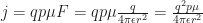
We consider a mobile hole and a fixed electron. The former drifts towards the latter, just driven by the Coulomb attraction, leading to an electric field felt by the hole of

with elementary charge 

Consequently, the recombination current of 
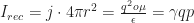
which defines the Langevin recombination prefactor 
In order to define the Langevin recombination rate 

with active layer thickness 


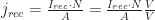
Replacing 


Comparing this equation to (*), we see that indeed

This is the classical result by Langevin, but derived with arbitrary radius as explained in the quote of [Nenashev 2010]. Thus, the explanation of the Coulomb radius for letting all charge carriers within recombine, and all without getting away, is not quite correct. In the paper by Nenashev et al., even though considering recombination (including diffusion!) in two dimensional systems, a possibly more intuitive approach for calculating an equivalent recombination rate is shown via the time until two charge carriers recombine.
However, Langevin recombination is only a start, as trapping of charge carriers is rather important in disordered organic semiconductors and its applications, e.g. organic solar cells. As a starter, see [Kirchartz 2011], [Street 2012], [Foertig 2012] etc.
P.S. Thanks to Jens L for making me aware of the “useless” 

just a typo: I_rec=J * Area
nice blog Carsten
gebi
Cheers! Carsten
If I understand correctly, the Langevin model considers homogeneous material system. Then what will happen when charge separation occurs at a clear-cut interface where two materials with distinctive properties come together? Just wondering.
Different electron and hole mobilities are already included in Langevin. An inhomogeneous material, e.g. phase separation or bilayer, will reduce the recombination probability probably by some (geometric) factor. Best, Carsten
Thanks for the explanation. So then bilayer structure may be suitable to study the recombination, since it has a clear cut interface, and well define bulk properties without mixing.
thx again.
In principle yes, but the charge carrier distribution is much more position dependent as compared to bulk heterojunctions!
Right, it is similar to the case in BHs having strong vertical phase separation. Well, it is still difficult to handle. :-(
Very nice site and initiative indeed!
I am new to this field and had a question related to donor acceptor materials. How and why do the two materials phase separate and form percolating paths? Any good reading on this topic?
Two different materials phase separate due to their different affinities to attract themselves or to attract the other material. If the two materials have a good affinity for each other than it is likely that the two materials will be very well mixed on an atomic scale whereas if they have a better affinity for being ‘with itself’ then you will get a phase mixture of some type. If you are a chemist then you will already know a lot about phase separation and how ‘like dissolves like’ from solution phase chemistry you merely extend this principle. More specifically though there is a whole field of study in polymer blend mixtures and the types of phase separation you will get, as it is important part of calculating polymer composite properties. I think you will find all you need to know and more in some review papers on that subject. Percolating paths happen naturally in nearly all mixed material systems due to chance arrangement.
Thanks for sharing this information. :)
Hi Ritu, in order to understand microphase separation, you might want to read some on Flory Huggins solubility theory. For a start in context with OSCs, I recommend Topham, Parnell, Hiorns, Journal of Polymer Science Part B: Polymer Physics, 2011, 49, 1131, and papers cited therein.